
In solar connector terminology, the C wire refers to the metal contact element inside a solar connector that gets crimped onto the stripped conductor of a photovoltaic cable. Unlike the HVAC industry’s “common wire,” this component is a precision-engineered crimping sleeve that creates the electrical connection between your solar cable and the plastic connector housing.
Understanding C wire crimping matters because a poorly executed crimp is the weakest link in any solar installation. Field failures from moisture ingress, high resistance connections, and mechanical pull-out trace back to improper crimping technique or tool selection. The crimping process isn’t just squeezing metal onto wire. You’re cold-welding two components together under thousands of pounds of force, creating a gas-tight connection that must withstand 25-plus years of thermal cycling, UV exposure, and mechanical stress.
The C wire itself is typically a tinned copper or copper alloy barrel with an hourglass profile, sized to match specific wire gauges common in solar arrays, usually 10 AWG through 14 AWG. When crimped correctly, the contact deforms around individual wire strands, displacing surface oxidation and creating multiple metal-to-metal contact points. This forms a connection with lower resistance than the wire itself.
This guide breaks down exactly what solar C wire contacts are, how the crimping mechanism works at a mechanical level, the differences between contact types and crimping tool options, and the quality standards that separate a reliable connection from a future service call. Whether you’re spec’ing components for a commercial array or wiring your first rooftop system, you’ll walk away knowing how to evaluate, select, and properly crimp these critical components.
What C Wire Means in Solar Connector Crimping
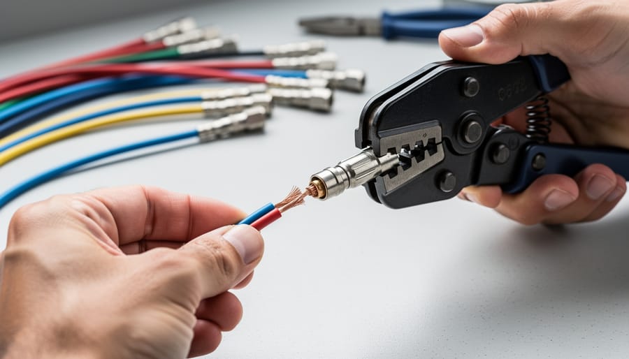
In solar connector crimping, the term “C wire” refers to the contact wire, the metallic conductor element that gets mechanically attached to the stripped end of a photovoltaic cable. This is fundamentally different from the HVAC industry’s “C wire” (common wire), which powers smart thermostats. When solar installers or technicians discuss C wire in the context of MC4 connectors and other photovoltaic junction systems, they’re talking about the actual copper conductor that carries DC current from solar panels through the system.
The contact wire serves as the electrical bridge between the solar cable and the connector assembly. Inside an MC4 or similar solar connector, you’ll find a metal contact pin or socket that gets crimped onto the stripped copper strands of your solar cable. This crimped contact then slides into the connector housing, where it mates with the opposite contact type to complete the circuit. Without a properly executed crimp on this contact wire, the entire solar installation becomes vulnerable to resistance heating, voltage drops, and eventual connection failure.
- Contact Wire (C Wire)
- The bare copper conductor portion of a solar cable that gets inserted into a crimp contact and mechanically compressed. This forms the current-carrying path within the connector assembly.
- Crimp Contact
- A metal terminal (pin or socket) that gets permanently attached to the contact wire through mechanical compression. The crimped assembly then inserts into the connector housing to establish the electrical connection.
- MC4 Connector
- The industry-standard waterproof connector system used in photovoltaic installations, consisting of male and female halves that lock together. Each half contains a crimped contact wire assembly.
- Barrel Crimp
- The specific crimping method that compresses a cylindrical metal sleeve around the contact wire. This creates the gas-tight, permanent mechanical and electrical bond required for solar applications.
Proper crimping of the contact wire matters because photovoltaic systems operate outdoors for decades, exposed to temperature swings, UV radiation, and moisture. A well-executed crimp creates a cold-weld bond between the contact and the copper strands, eliminating air gaps that would otherwise oxidize and increase resistance. This isn’t just about making an electrical connection, it’s about creating a connection that will maintain its integrity through 25-plus years of environmental stress while carrying potentially high DC currents without generating heat or voltage loss.
How C Wire Crimping Works
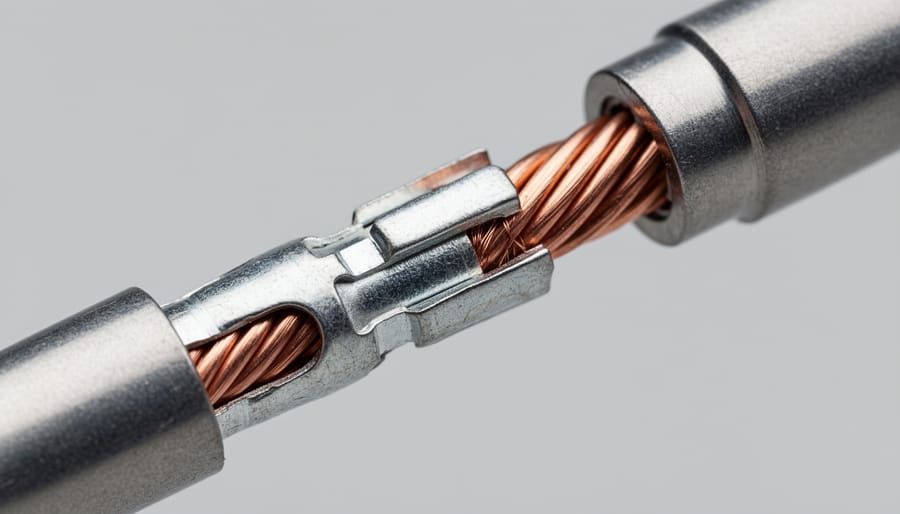
Crimping a contact wire to a solar connector is a cold-forming process that creates a permanent mechanical and electrical bond without heat. When you insert a stripped wire into a metal contact barrel and apply compression through a crimp tool, the barrel deforms around the conductor strands, trapping them within a precisely controlled crimp zone. This compression must be substantial enough to displace metal and eliminate air gaps, yet controlled enough to avoid crushing the copper strands or fracturing the contact material.
The process relies on two distinct crimp zones working in tandem. The conductor crimp zone compresses directly onto the bare copper strands, creating multiple metal-to-metal contact points as the barrel’s inner surface conforms to the irregular geometry of individual wire strands. The insulation crimp zone, positioned further back on the contact, compresses onto the wire’s insulated portion to provide strain relief and prevent the conductor from pulling free under mechanical stress. Each zone requires different compression characteristics, the conductor zone needs aggressive deformation to maximize electrical contact, while the insulation zone needs gentler compression to grip without cutting through the jacket.
As the crimp tool’s die closes around the contact barrel, metal flows plastically under extreme localized pressure. This plastic deformation breaks through surface oxides on both the copper wire and the contact material (typically tin-plated copper or copper alloy), bringing clean metal surfaces into direct contact. The applied force, measured in tons for larger solar connectors, creates sufficient pressure to initiate cold welding at molecular contact points between the wire strands and barrel interior. Unlike fusion welding, this process occurs at room temperature through mechanical compression alone.
The gas-tight seal is critical for outdoor photovoltaic applications. When compression forces the barrel material to flow around and between individual copper strands, it eliminates air pockets and creates a hermetic barrier against moisture and atmospheric oxygen. This oxygen exclusion prevents the formation of copper oxide at the connection interface, which would otherwise increase electrical resistance over time and generate heat under high current loads. Field tests show that properly crimped solar connections maintain contact resistance below 0.5 milliohms for decades, while inadequate crimps can develop resistances ten times higher within months of exposure.
Achieving proper crimping force requires matched tooling and contact specifications. Ratcheting crimp tools use mechanical advantage and controlled die geometry to ensure consistent compression depth, preventing both under-crimping (insufficient metal deformation) and over-crimping (strand damage or barrel fracture). The crimp profile typically forms a hexagonal or trapezoidal cross-section, with precise indent depth specifications that vary by wire gauge and contact manufacturer.
This cold-forming approach proves superior to soldering for solar applications because it creates a mechanical bond immune to thermal cycling. Solar connectors experience temperature swings from sub-zero nights to 80°C daytime exposure, cycles that cause differential thermal expansion in soldered joints and eventual solder fatigue. Crimped connections, bonded through physical interlocking rather than metallurgical fusion, maintain their integrity across these temperature extremes without degradation.
Components of Solar Connector C Wire Assembly
Contact Pin vs. Contact Socket
Solar connectors use two distinct contact types that must mate correctly to complete a circuit: contact pins (male) and contact sockets (female). The pin features a solid cylindrical conductor that inserts into the socket, while the socket contains spring-loaded fingers that grip the pin and maintain constant pressure for electrical continuity.
Contact pins typically have a simpler crimp barrel design, a hollow cylinder that compresses around stripped wire strands. When crimped, the barrel collapses inward, creating multiple metal-to-metal contact points between the pin material and each copper strand. The pin’s exterior remains smooth to slide cleanly into its mating socket.
Contact sockets require more complex manufacturing because they must grip the pin firmly while allowing easy insertion and removal. The crimp barrel functions identically to pin barrels, compressing around the wire conductor. However, the socket’s forward section contains split fingers or leaves that flex outward when a pin enters, then spring back to maintain contact pressure.
Both contact types use a secondary crimp or strain relief that compresses onto the wire’s insulation jacket, preventing mechanical stress from transferring to the electrical connection. This dual-crimp design, one for the conductor, one for the insulation, ensures the crimped joint withstands vibration, thermal cycling, and physical movement without degrading electrical performance.
Wire Gauge Compatibility
Solar installations typically use three primary wire gauges, each matched to specific current-carrying requirements and crimp contact designs. 10 AWG wire is the standard for main array runs and high-current connections, handling up to 40 amps in sunlight with minimal voltage drop. This thicker conductor requires larger crimp barrels, typically 6mm or 7mm diameter, to accommodate the increased cross-sectional area and ensure full compression of all wire strands.
12 AWG wire serves mid-range installations, suitable for branch circuits and shorter runs where currents stay below 30 amps. Its crimp contacts use intermediate barrel sizing, usually 5mm to 6mm, creating a balanced connection that’s neither over-compressed nor loose.
14 AWG wire appears in lower-power arrays and residential systems with modest current demands, typically under 20 amps. These thinner conductors pair with smaller 4mm to 5mm crimp barrels. Using an oversized contact on 14 AWG wire creates gaps that allow strand movement and eventual connection failure, while forcing a larger wire into an undersized contact prevents proper compression.
Each gauge requires matching die sets in your crimp tool, using 10 AWG dies on 12 AWG wire produces an incomplete crimp, while 14 AWG dies on 10 AWG wire won’t close properly. Just as specifications matter in network cabling, precise gauge-to-contact matching determines whether your solar connection will last decades or fail within months.
Types of Crimp Tools for Solar C Wire Connections
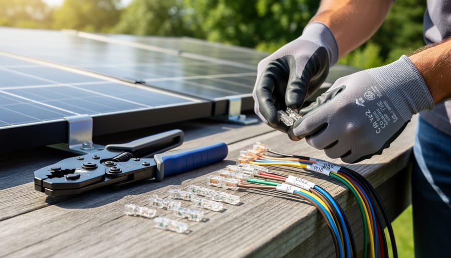
Solar connector crimping requires specialized tools designed to deliver precise compression force without damaging wire strands or connector contacts. The right tool depends on installation scale, production volume, and whether you’re working in the field or a manufacturing facility.
Ratcheting Crimp Tools
Ratcheting crimpers are the most common choice for field installations and smaller solar projects. These hand-operated tools feature a ratchet mechanism that prevents the jaws from opening until the crimp cycle completes, ensuring consistent compression across every connection. They typically deliver 2-4 tons of force and work well with MC4 connectors and standard solar wire gauges. Ratcheting tools are portable, require no power source, and allow installers to choose the right crimping tool based on the specific connector system they’re using. The main limitation is fatigue during high-volume installations, as each crimp requires manual force.
Hydraulic Crimpers
Hydraulic crimping tools use fluid pressure to generate significantly higher compression force (6-12 tons) with minimal physical effort from the operator. Available in both manual pump and battery-powered versions, hydraulic crimpers excel at larger wire gauges and when processing dozens of connections daily. Battery-hydraulic models have become standard for professional solar installers working on commercial arrays, where speed and ergonomics matter over extended periods. The trade-off is higher initial cost and the need to maintain hydraulic seals.
| Tool Type | Crimp Force Range | Typical Application | Precision Level |
|---|---|---|---|
| Ratcheting | 2-4 tons | Field installations, residential | High (manual control) |
| Hydraulic | 6-12 tons | Commercial arrays, daily use | Very high (consistent pressure) |
| Automatic | 8-15 tons | Manufacturing, bulk production | Exceptional (programmable) |
Automatic Crimp Machines
Automated crimping systems are reserved for manufacturing environments and large-scale solar component production. These machines feature programmable crimp profiles, wire feeding mechanisms, and quality verification sensors that can process hundreds of connections per hour with minimal variation. While prohibitively expensive for field work, automatic crimpers ensure the repeatability and traceability required for certified solar component manufacturing. Some hybrid semi-automatic tools bridge the gap for high-volume installers who need production speed without full automation complexity.
Applications and Uses of C Wire Crimping in Solar Installations
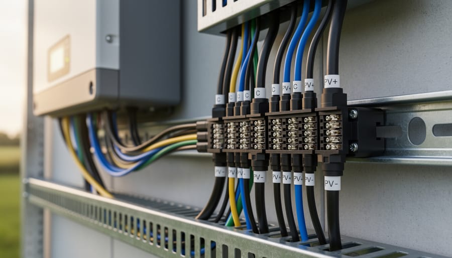
C wire crimping forms the backbone of every DC electrical connection in photovoltaic systems. In string-to-string connections, installers crimp MC4 or compatible contacts onto wire ends to create the series links that build voltage across multiple panels. A typical residential installation requires 20 to 40 of these crimped connections to complete the array wiring, and each joint must maintain conductivity through decades of thermal cycling and weather exposure.
Panel-to-combiner box wiring relies on crimped contacts to transition from individual panel outputs to the home run cables feeding inverters or charge controllers. These connections handle the full current of combined strings, often 30 to 50 amps in residential systems and considerably higher in commercial arrays. The mechanical reliability of properly crimped contacts prevents voltage drop and heat buildup that would degrade system performance over time.
Array interconnections between roof sections or ground-mount racks depend on crimped wire joints to maintain electrical continuity across physical gaps. Unlike twist-on wire connectors or electrical tape splices, crimped solar contacts create a gas-tight seal that prevents oxidation at the copper interface. This matters in outdoor environments where moisture infiltration and temperature swings would quickly compromise inferior connection methods.
DC circuit assembly throughout the system uses crimped contacts for every junction: combiner box inputs, breaker connections, disconnects, and inverter terminals. The cold-welding effect of proper crimping produces a molecular bond between contact and conductor that resists vibration loosening and thermal expansion better than screw terminals. This stability is why electrical codes and manufacturer warranties specify crimped connections rather than field-soldered joints, which introduce heat damage risk and inconsistent quality in production environments.
Proper Crimping Technique and Quality Standards
A reliable crimp starts with precision at every stage. Begin by stripping the wire to the exact length specified by the connector manufacturer, typically 6 to 8 millimeters for most MC4-style contacts. Use dedicated wire strippers, not side cutters, to avoid nicking individual strands. Even one damaged strand reduces the contact area and compromises conductivity. After stripping, inspect the exposed conductor: all strands should remain intact and parallel, with no splaying or breakage.
Insert the prepared wire fully into the contact barrel until the insulation meets the stop point inside the crimp chamber. The conductor must reach the end of the barrel; partial insertion creates high-resistance connections that generate heat under load. Once positioned, select the appropriate die size for your wire gauge and contact type. Referencing a crimp tool buying guide helps ensure you have the correct tooling matched to your specific connectors and cable sizes.
Position the crimping die over the contact barrel, aligning it with the crimp zone markings molded into most quality contacts. Compress the tool fully through its complete ratchet cycle, partial crimps from incomplete strokes are a leading cause of field failures. The barrel should form a hexagonal or B-crimp profile with uniform compression around the circumference. Asymmetric or incomplete compression indicates misalignment or improper die selection.
Verify your work with a pull test immediately after crimping. Grasp the wire and connector housing, then apply firm tension, a proper crimp withstands at least 15 pounds of force without separation. The wire should not slide, rotate, or extract from the contact. If it does, discard the assembly and analyze what went wrong before attempting another crimp.
Industry standards provide measurable benchmarks for crimp quality. UL 2703 specifies mechanical and electrical requirements for photovoltaic wire connectors, including pull-force thresholds and contact resistance limits. TÜV certification verifies that crimped assemblies maintain their integrity through thermal cycling, UV exposure, and environmental stress testing. IEC 62852 establishes performance criteria for DC connectors in photovoltaic systems, including crimp durability specifications. These standards aren’t abstract guidelines, they define the minimum acceptable performance for connections that must function reliably for 25 years or more in outdoor conditions.
Common Crimping Mistakes and How to Avoid Them
Even experienced installers make crimping errors that compromise solar connections. Over-crimping deforms the contact barrel excessively, fracturing conductor strands and creating stress points where corrosion begins. The barrel wall becomes thin and weakened, reducing mechanical pull strength by up to 40%. Conversely, under-crimping leaves gaps between wire strands and contact metal, increasing resistance and generating heat that can melt insulation or damage photovoltaic modules over time.
Incorrect wire strip length causes two distinct problems. Stripping too much copper exposes bare conductor outside the contact barrel, creating a shock hazard and potential short-circuit point. Stripping too little prevents proper insertion depth, leaving strands outside the crimp zone where they cannot form reliable connections. Measure strip length precisely using the contact manufacturer’s specification, typically 6-8mm for standard MC4 contacts.
Strand damage during preparation weakens the entire assembly. Nicking conductors while stripping insulation, twisting strands unevenly, or allowing stray wire fragments to remain all reduce effective conductor cross-section and create resistance hot spots. Always use sharp, calibrated wire strippers and inspect the stripped end before insertion.
Using the wrong die size for your wire gauge produces inadequate compression geometry. A 10 AWG die used on 12 AWG wire under-crimps the connection, while a 14 AWG die on 12 AWG wire over-compresses and damages strands. Match your crimping tool’s die precisely to both wire gauge and contact manufacturer specifications. Selecting the correct die size ensures proper barrel compression and optimal electrical contact.
Prevent these errors through systematic quality control. Perform pull tests on sample crimps at the start of each work session, inspect finished connections visually for proper barrel compression, and replace worn dies that no longer produce consistent crimp geometry. Keep a wire gauge reference card with your tool kit to eliminate size-matching errors.
Frequently Asked Questions
Can I reuse a crimped solar connector if I make a mistake?
No, crimped connections cannot be undone without damaging the contact or wire. Once compressed, the metal deformation is permanent. If you crimp incorrectly, you’ll need to cut off the connector and start fresh with a new contact pin or socket.
How much force should I apply when crimping a solar C wire?
You shouldn’t manually apply force, the tool does the work. Ratcheting crimpers automatically control pressure and won’t release until the crimp cycle completes. Forcing the handles or releasing early produces weak connections that fail pull tests.
Do I need different crimp dies for copper versus tinned copper wire?
No, the same crimp dies work for both bare and tinned copper conductors of the same gauge. Tinned wire actually crimps more reliably because the tin coating prevents oxidation at the contact interface and improves long-term conductivity.
What’s the minimum pull force a properly crimped solar connection should withstand?
Industry standards require crimped solar connectors to withstand at least 90 pounds of pull force for 10 AWG wire and 60 pounds for 12 AWG. Most quality crimps exceed these minimums significantly when executed with calibrated tools and correct technique.
These specifications matter because solar installations face thermal cycling, vibration, and decades of outdoor exposure. A crimp that barely meets minimum standards today may fail years down the line when expansion and contraction stress the connection. Professional installers verify every critical crimp with a pull tester, especially on roof-mounted arrays where accessing failed connections later requires expensive equipment and labor.
Understanding C wire crimping represents far more than learning a simple mechanical task. It forms the foundation of reliable solar installations that must perform flawlessly for 25 years or longer under demanding outdoor conditions. Every crimped connection in your photovoltaic array serves as a critical junction point where electrical energy transfers from one component to the next, making proper technique non-negotiable.
The difference between a correctly crimped contact and a marginal connection determines whether your system delivers consistent power or suffers from voltage drops, heat buildup, and eventual failure. Field technicians who master the fundamentals, proper wire preparation, correct die selection, adequate compression force, and thorough verification, protect both system performance and safety. These skills prevent the slow degradation that turns invisible crimping errors into costly service calls years after installation.
Quality crimped connections don’t just happen. They result from understanding the mechanical principles, respecting component specifications, using calibrated tools, and maintaining consistent standards across every joint. When you treat each crimp as a permanent weld that must outlast decades of thermal cycling and environmental stress, you build solar systems that justify the investment and deliver the clean energy reliability our grid transition demands.